Some students with physical disabilities may already use switches to communicate and/or control their devices.
Most switches output to a 3.5mm jack (male connector) and make a connection between the tip and the sleeve when the switch is pressed. These switches can be connected to a micro:bit to be used as an alternative input (instead of button A and B, for example). In this case they could be used with a micro:bit as an alternative input, without soldering, in one of the following ways:
Connecting to a pin
Ross Atkin Associates
Ross Atkin Associates
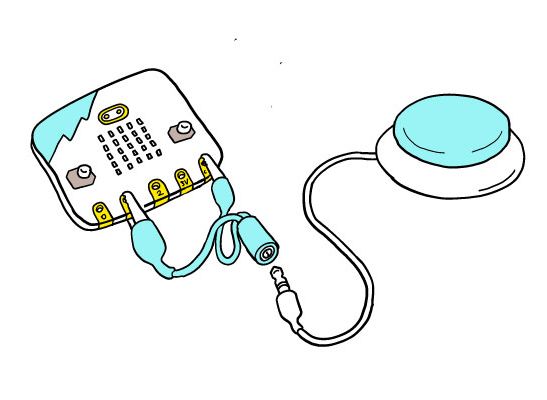
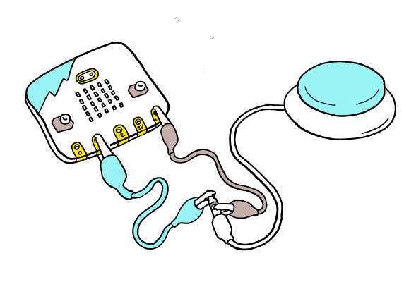
You can connect the switch to a pin of the micro:bit, to use as an input to your program. It is possible to buy a cheap audio jack to alligator clip cable to go from a 3.5mm switch cable to two alligator (crocodile) clips. Connect these to the ground (GND) pin and to one of the input pins (pin 0, 1 or 2). If you do not have an adapter available, you can use crocodile clips (or foil) to attach directly from the tip and sleeve of the switch jack, to the ground pin and pin 0, 1 or 2. This will be a less stable solution compared to using an adapter.
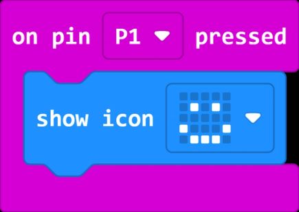
If you are using the switch as a pin input in one of these two ways, you will need to modify your student’s code to use an ‘on pin pressed’ block rather than using a button press, for example:
Connecting to a button pin via an edge connector
Ross Atkin Associates
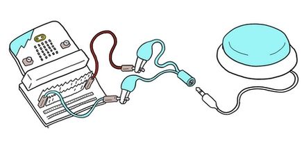
If you want a student to use exactly the same code project as their peers, without needing to adapt from a button input to a pin input, you can use an edge connector with jumper wires and crocodile clips, to connect directly to button A or B’s connection, and ground (GND). You will also need the adaptor described in the previous section, or connect directly to the tip and sleeve of the audio cable.
Other notes on switch use
It is noted that some accessible devices use the switch to run power through, especially devices that have been adapted to be switch operated. In this case, you would need a more involved circuit including a switch relay.
If you do not have assistive switches, consider adaptive gaming switches like the Logitech G Adaptive Gaming Kit for Xbox, which provides 12 different input switches. Alternatively, you can build your own switch using PrintLab 3d printable switch designs or request one from the Maker's Making Change device library, which also provides build-your-own resources.
You can also build a DIY switch by creating any circuit in which the circuit is closed by an action the student takes. For example, the pressure switch alarm uses aluminium foil to create a switch which is operated by pressing the two sides of cardboard together. This sip puff switch uses a cardboard and aluminium foil contraption to close a circuit when a user blows through a straw.
Some micro:bit projects incorporate DIY switches to make an inclusive activity, for example this reaction game and banana keyboard.
See also the access:bit prototype, still under development, which will allow a student to operate both buttons and 3 main pins on the micro:bit directly using a switch.
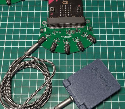
John Vidler, the Access:bit write up